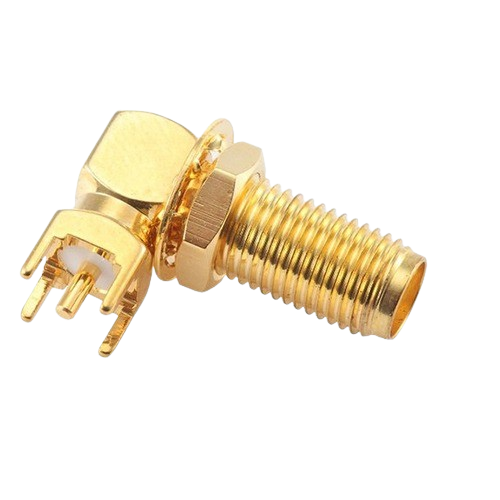
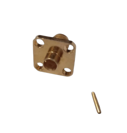
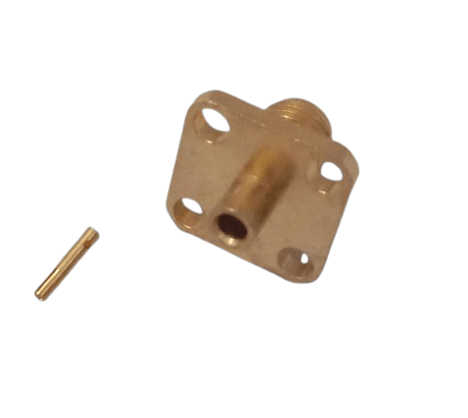
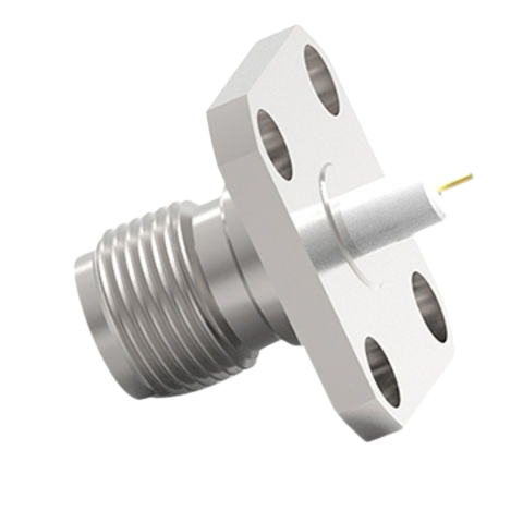
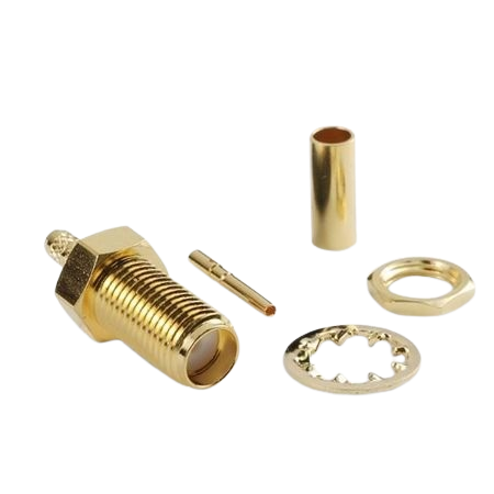
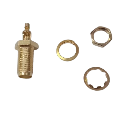
Preparation: – Inspect the PCB : Ensure that the PCB is prepared with the correct footprint, including four mounting holes or pads that correspond to the SMA connector’s pins. – Prepare the Connector: Ensure that the SMA female connector is clean and ready for assembly. Prepare the Cable: – Strip the Cable: Prepare the RG-0.86 coaxial cable by stripping it to expose the central conductor and shield: – Remove the Outer Jacket: Strip away the outer jacket to reveal the braided shield and dielectric insulation. – Expose the Shield: Carefully remove or fold back the braided shield. – Strip the Dielectric: Strip the dielectric insulation to expose the central conductor. Follow the manufacturer’s specifications for the correct strip lengths. Assemble the Connector: – Insert the Central Conductor: Insert the stripped end of the central conductor into the pin of the SMA female connector. Ensure that it is properly aligned and inserted. – Crimp or Solder the Central Conductor: Depending on the connector design, crimp or solder the central conductor. For soldering, heat the pin and apply solder to create a secure connection. Position and Mount the Connector: – Align the Connector: Position the SMA female connector so that its four mounting pins align with the corresponding PCB holes or pads. – Secure the Connector: Hold the connector in place, either manually or using a fixture. Soldering Steps: – Solder the Pins: – Heat each pin of the connector with a soldering iron. – Apply solder to each pin and its corresponding PCB pad, ensuring that the solder flows around the pin and pad for a solid connection. – Avoid excessive solder to prevent solder bridges and ensure clean, controlled joints. Final Steps: – Inspect the Solder Joints: Check each solder joint to ensure it is properly bonded. Look for clean, shiny joints without cold solder or solder bridges. – Clean the Area: Use isopropyl alcohol or another suitable cleaning agent to clean the soldered area and remove any flux residue. – Test the Connection: Use RF testing equipment, if available, to confirm that the SMA connector performs correctly and meets the required specifications for signal integrity and performance Applications; – PB Mounting : The SMA female connector with four holes is designed to be mounted on a PCB, providing a robust and secure connection for RF applications. – High-Frequency Connections: Suitable for high-frequency applications, where RG-0.86 cable is used for its low attenuation and small size. – Durability: The four-hole design provides enhanced mechanical stability, making it ideal for applications that experience physical stress or movement. Advantages: – Secure Mounting: The four-hole design ensures a strong and stable mechanical connection to the PCB, which is important for maintaining signal integrity and durability. – High-Frequency Performance: The SMA connector is designed to handle high-frequency signals effectively, ensuring reliable performance in demanding RF applications.